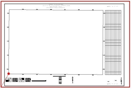
In Microstation blocks are called cells. In this article we will see how to do it and the logic that makes them differ from AutoCAD blocks.
1. For what purpose the cells are used
Unlike the GIS where symbolism is dynamic from a point and its attributes, in the CAD objects must be placed objects on the geometry as:
- In 2D constructive plans: the representative symbols of toilets, sinks, lamps, sockets, trees, etc.
- In property maps: the symbols of public building, bridge, church, school, etc.
Other common cases, usually tends to be the framework around a map, which is set to a specific paper size and where are detailed the responsibilities of those who carry out the project.

2. How to build cells in Microstation
Let us assume that the above figure is the block that we want to create. It is a frame for a 1:1,000 map on a 24″36″ sheet.
The red contour corresponds to this sheet in 1:1000’s scale (609.60 meters x 914.40 meters), then I’ve taken out space according to the plotter margins and within I have drawn the module with the necessary legends.
 The red dot is an insertion point for my interest, because with this displacement vector the 1:1,000’s grid is just inside, something that I’ll explain in a future article when I’ll discuss how to create a print layout using Microstation.
- Select the objects that we are interested in converting to block, excluding the external red frame.
- Activate the management cells panel. To do this, in Microstation 8.8 case hold it down and drag, in Microstation V8i case press right mouse button and choose the option to deploy as a floating toolbar.
- Select the button first and then the search magnifying glass.
![clip_image003[4] clip_image003[4]](https://egeomate.com/wp-content/uploads/2013/06/clip_image0034-jpg.jpg)
This will pull up a panel of block libraries.
- It creates a .cel library type; this is done via File / New. If you already have a library, it is loaded with File / Attach.
![clip_image004[4] clip_image004[4]](https://egeomate.com/wp-content/uploads/2013/06/clip_image0044-jpg.jpg)
Next, we need to tell it where is the origin point of our block, which will be the insertion point when we call to it.
This is done using the fourth command of the cells bar, and clicking on the inner corner of the UTM grid, as shown in the graph.
From this point, it is activated the “Create” button.
- We name the block, in this case Marco1000 and the description Marco 1:1,000. See you can already pre view.
![clip_image005[4] clip_image005[4]](https://egeomate.com/wp-content/uploads/2013/06/clip_image0054-jpg.jpg)
3. How to load existing cells
To call them, double-click on the block that interests us, and they are ready to insert, with option to choose the scale, rotation and location point.
In case you want to load existing blocks, AutoCAD only allows loading blocks that are in a dxf/dwg file and is done with the Design Center command.
Microstation allows more formats:
- Microstation libraries (.cel y .dgnlib)
- CAD files (.dgn, .dwg, .dxf)
- GIS files (.shp, .tab, .mif)
- Other formats (.3ds, .obj, .3dm, .skp, .impx)
To view the available blocks in the file, select “Display all cells in path” option, you can also bring the file as a block.
To ungroup a file, use the Drop command by activating the cell option.
 Autocad Software, Bentley Microstation, Gis Google Earth, Gis System Geomate Provides Services For Complete Gis Software And Solutions, Autocad Software, Autocad Courses, Bentley Microstation, Microstation Software, Gis Google Earth, Open Source Gis And More.